Improper wire rope clip installation remains a leading cause of rigging hardware failure across industrial sites. A correctly installed termination retains up to 80% of the wire rope's breaking strength. However, a poorly installed one can reduce this capacity to below 50% or cause sudden, catastrophic slipping. Many operators underestimate the precise physics required to secure these connections safely. Failing to follow strict orientation rules or torque specifications puts personnel and property at severe risk. You cannot afford to guess when lives depend on overhead loads. This guide provides a definitive, standards-compliant approach to securing your lines. We will cover hardware selection, the critical “never saddle a dead horse” rule, torque requirements, and post-load inspection. Rigging professionals, safety inspectors, and procurement managers will learn exactly how to evaluate compliance standards and source reliable fittings.
Key Takeaways
- Hardware Selection Dictates Safety: Drop-forged clips are mandatory for critical or overhead loads; malleable clips are strictly for non-critical, static applications.
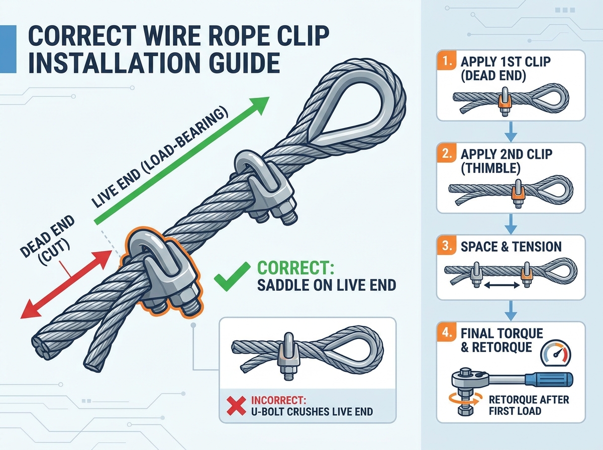
- Orientation is Non-Negotiable: The saddle must always sit on the live (load-bearing) end of the wire rope, while the U-bolt crosses the dead (cut) end.
- Torque is Dynamic: Wire rope shrinks in diameter under initial tension. Retorquing clips after applying the first load is a mandatory compliance step, not a recommendation.
- Follow the Formula: Turnback length, clip spacing, and the total number of clips depend strictly on the rope's diameter.
Evaluating Wire Rope Clip Types for Your Project
Selecting the correct hardware involves matching metallurgical properties to your application's specific risk profile. Rigging operations demand absolute certainty. You must evaluate the load, environmental conditions, and potential impact of a failure. A high-quality wire rope clamp provides a reliable grip, but only if you choose the right material. Understanding the physical differences between forged and cast metals will prevent dangerous procurement mistakes.
Drop-Forged U-Bolt Wire Rope Clips
Drop-forged clips represent the industry standard for heavy-duty applications. Manufacturers heat solid steel and hammer it into shape using massive pressure. This forging process aligns the internal metallurgical grain structure. It creates superior strength, flexibility, and durability.
- Best for: Critical loads, overhead lifting, heavy rigging, guy wires, and permanent structural supports.
- Characteristics: They resist impact and shock loads effectively without shattering. You can easily identify them by their heavy, robust appearance. They also feature distinct manufacturer markings indicating size, traceability, and origin.
Malleable U-Bolt Wire Rope Clips
Malleable cast iron clips serve a completely different purpose. Foundries pour molten metal into molds rather than forging solid steel. This casting process leaves the metal brittle compared to forged alternatives.
- Best for: Fencing, guard rails, and non-load-bearing visual barriers.
- Risk Warning: They are highly prone to fracturing under shock loads or sudden tension drops. You must never use a malleable U bolt wire rope clip for overhead lifting. Do not use them where failure risks injury or severe property damage. They remain strictly for static, light-duty applications.
Fist Grip (Twin-Base) Clips
Fist grip clips offer a unique design alternative to traditional U-bolts. They feature two identical grooved saddles connected by threaded bolts.
- Best for: Applications requiring faster installation or where orientation errors pose an unacceptably high risk.
- Characteristics: The twin-base design makes it impossible to install them backward. Because both sides feature a saddle, they will not crush the rope. You generally need fewer clips per termination. However, they carry a higher unit cost, which may impact your budget on large-scale operations.
Wire Rope Clip Type Comparison Chart
| Clip Type | Manufacturing Process | Primary Application | Key Advantage / Disadvantage |
| Drop-Forged U-Bolt | Heated and hammered steel | Overhead lifting, critical loads | High impact resistance / Requires strict orientation |
| Malleable U-Bolt | Cast iron poured into molds | Fencing, static barriers | Cost-effective / Brittle, prone to shock failure |
| Fist Grip (Twin-Base) | Forged twin saddles | Fast installation, foolproof setups | Impossible to install backward / Higher unit cost |
Preparation: Calculations and Rigging Hardware Requirements
Proper preparation prevents catastrophic field failures. You must perform specific calculations before assembling any rigging hardware. Guesswork has no place in load securement. Taking time to verify measurements ensures your assembly achieves maximum holding power safely.
Matching Hardware to Rope Diameter
The clip size must perfectly match the nominal diameter of your wire rope. You cannot use a 5/8-inch clip on a 1/2-inch rope. Undersized clips will pinch and severely damage the outer steel strands. Oversized clips fail to grip the rope sufficiently, allowing it to slide under tension. Always verify the stamped size on the saddle base before beginning installation.
Determining Clip Quantity
Industry standards dictate strict rules for hardware quantities. Organizations like OSHA and ASME B30.9 provide comprehensive guidelines. The minimum number of clips depends entirely on the rope diameter. For example, a 1/2-inch rope generally requires at least three clips. Larger diameters require progressively more clips to secure the load effectively. Never use fewer clips than the manufacturer or standard requires. Doing so compromises the entire assembly.
Calculating Turnback Length
Turnback length refers to the exact amount of rope you fold back to create the eye. This length ensures you have enough room to apply all necessary clips at the correct spacing. A standard 1/2-inch rope requires approximately 11.5 inches of turnback. You must measure this distance accurately before making your first bend. Shortchanging the turnback length forces you to cramp the clips together, destroying their holding friction.
Typical Hardware Requirements by Rope Diameter (Example Reference)
| Rope Diameter (Inches) | Minimum Number of Clips | Amount of Rope Turnback (Inches) | Torque Required (Ft-Lbs) |
| 1/4" | 2 | 4.75" | 15 |
| 1/2" | 3 | 11.5" | 65 |
| 3/4" | 4 | 18.0" | 130 |
| 1" | 5 | 26.0" | 225 |
The Role of Thimbles
We strongly recommend using a heavy-duty thimble inside the loop. The thimble maintains the correct wire rope fitting radius. It prevents the rope from flattening or kinking under severe tension. A crushed eye loses significant breaking strength immediately. Thimbles also protect the inner wires from fraying directly against the connecting shackle, hook, or pin.
The 5-Step Wire Rope Clip Installation Framework
Executing a flawless wire rope clip installation requires discipline. Follow this sequential framework to guarantee maximum holding power. Skipping steps or altering the order will compromise the final termination.
Step 1: Apply the First Clip at the Dead End
Begin by measuring your required turnback length. Place your first clip exactly one base-width away from the dead (cut) end of the rope. You must ensure the U-bolt sits directly over the dead end. The grooved saddle must rest on the live (load-bearing) line. Tighten the nuts evenly to the manufacturer's recommended torque. This step secures the tail and prevents the strands from unlaying during further handling.
Step 2: Apply the Second Clip at the Thimble
Next, position the second clip as close to the thimble as possible. You must not bind or crush the thimble edges during this step. Ensure the U-bolt again crosses the dead end, matching the orientation of the first clip. Hand-tighten the nuts for now. Do not fully torque them yet. Leaving them hand-tight allows the rope to shift, stretch, and adjust naturally during the tensioning phase.
Step 3: Space and Apply Intermediate Clips
If your rope diameter requires more than two clips, you must install the intermediate ones now. Space the remaining clips evenly between the first two. Uniform spacing is critical for structural integrity. It distributes the gripping force evenly across the entire termination length. Double-check your orientation to ensure every single saddle sits securely on the live end.
Step 4: Apply Tension to the Assembly
Before final tightening, you must seat the rope properly. Apply a light operational load to the assembly. Alternatively, use a come-along tool to pull the live line tight against a solid anchor. This action pulls all loose slack out of the loop. It seats the rope firmly and uniformly around the curved thimble contour, preventing future shifting.
Step 5: Final Torque Application
Finally, grab a recently calibrated torque wrench. Tighten all nuts evenly across every clip in your assembly. Alternate your wrench from one nut to the other on the same clip. This alternating method keeps the saddle perfectly level against the rope. Continue this alternating pattern until you meet the manufacturer’s specific torque requirement. Never guess the torque value, as visual estimates are inherently flawed.
Critical Installation Errors: Why You "Never Saddle a Dead Horse"
Even experienced riggers make mistakes when rushing through field installations. Understanding the mechanics behind these common errors helps you prevent them. A single mistake compromises the entire wire rope termination, putting your entire crew in danger.
The Mechanics of the Error
"Never saddle a dead horse" serves as a mandatory memory aid across the rigging industry. Placing the U-bolt over the live (load-bearing) end is a fatal flaw. The narrow U-bolt applies highly concentrated pressure. It physically crushes and deforms the load-bearing wires under load. This deformation creates a severe weak point exactly where the rope holds the most tension. The saddle features a grooved, wider surface specifically designed to support the live end without crushing its internal core.
Improper Spacing
Spacing dictates overall holding power. Placing clips too close together limits their grip. The rope essentially acts as a single rigid block, reducing the necessary friction required to hold the dead end. Conversely, placing them too far apart allows the dead end to slip backward gradually under heavy loads. You must follow the exact spacing formula provided by your hardware manufacturer to ensure balanced friction.
Skipping the Torque Wrench
Many operators rely on "feel" to tighten nuts using standard wrenches. This practice is highly dangerous. Over-tightening physically severs internal wire strands, weakening the rope invisibly from the inside out. Under-tightening results in insufficient friction, leading to immediate load drops when tension spikes. A calibrated torque wrench acts as a low-cost insurance policy against liability, injury, and catastrophic failure.
Compliance, Testing, and Post-Installation Maintenance
Installation marks the beginning, not the end, of the safety process. Ongoing maintenance ensures the connection remains safe throughout its entire service life. Environmental factors and dynamic loads constantly degrade hardware components.
The "First Load" Retorque Rule
Wire rope possesses dynamic physical properties. It stretches significantly when you apply an initial load. As the core settles and the strands stretch, the rope's overall diameter actually shrinks. Because the rope shrinks, the nuts you just torqued perfectly will loosen. Retorquing clips immediately after applying the first load is an absolute industry mandate. It is not an optional recommendation. Skipping this step practically guarantees future slippage.
Ongoing Inspection Routines
You must inspect your assemblies regularly. Establish a strict routine schedule based on usage frequency and environmental exposure. Check for the following warning signs during your visual inspections:
- Crushed, flattened, or severely kinked outer strands near the saddles.
- Cracked, deformed, or heavily corroded clip bodies.
- Stripped threads on the U-bolts or completely missing nuts.
- Slipped thimbles that no longer sit tightly in the eye of the rope.
When to Retire Hardware
Knowing exactly when to discard hardware prevents accidents. You must remove a cable clip from service immediately if it shows any signs of plastic deformation. Deep gouges, severe rust, or bent U-bolts mean the clip is dead. Furthermore, if you do not know the history of its load exposure, discard it entirely. Never risk a heavy lift on hardware carrying an unknown past.
Conclusion
Proper wire rope termination operates as a strict science. It demands a thorough understanding of metallurgy, physics, and compliance frameworks. Adhering to manufacturer torque specifications and strict orientation rules guarantees a secure, reliable hold.
To maintain a safe working environment, take the following action steps immediately:
- Audit your current rigging hardware inventory to identify any unrated or damaged components.
- Discard all unrated or malleable clips currently used in active lifting environments.
- Source only drop-forged clips from certified manufacturers who provide verifiable load ratings and material traceability.
- Implement a mandatory, logged torque wrench policy for all field installations and maintenance routines.
FAQ
Q: Can you reuse wire rope clips?
A: You can sometimes reuse saddles if they pass strict visual inspections for cracks and deformation. However, you should generally replace U-bolts and nuts. High torque stretches the threads over time, compromising their gripping strength. Never reuse any hardware if you do not know its past load exposure.
Q: Are fist grip clips better than U-bolt clips?
A: Fist grips eliminate the "dead horse" orientation error since they feature two identical saddles. They also prevent crushing the rope. However, U-bolt clips remain more widely available and highly cost-effective for large-scale projects. Your choice depends entirely on your specific budget and installation speed requirements.
Q: Do wire rope clips reduce the capacity of the rope?
A: Yes, they do. A properly installed termination typically results in an 80% efficiency rating of the rope's nominal breaking strength. You must calculate this 20% reduction into your Working Load Limit (WLL) to ensure safe lifting operations at all times.

 English
 العربية
 Français
 Русский
 Español
 Português
 Deutsch
 italiano
 日本語
 한국어
 Nederlands
 Tiếng Việt
 ไทย
 Polski
 Türkçe
 አማርኛ
 ພາສາລາວ
 ភាសាខ្មែរ
 Bahasa Melayu
 ဗမာစာ
 தமிழ்
 Filipino
 Bahasa Indonesia
 magyar
 Română
 Čeština
 Монгол
 қазақ
 Српски
 हिन्दी
 Slovenčina
 Slovenščina
 Norsk
 Svenska
 українська
 Ελληνικά
 Suomi
 Հայերեն
 עברית
 Dansk
 اردو


