Securing a load with the incorrect number of wire rope clips compromises the entire lifting or guy-wire system. It risks catastrophic failure and severe regulatory penalties. You cannot rely on guesswork when human lives and heavy loads hang in the balance. In industrial and commercial applications, determining the correct clip quantity is a strict mathematical requirement. Rope diameter and industry standards dictate the exact rules. Organizations like OSHA and ASME provide these safety frameworks. A single missing clip can cause disastrous load slippage.
This guide breaks down the exact specifications for safe terminations. You will learn the engineering rules behind clamp spacing. We also explore the criteria for evaluating heavy-duty hardware. Following these steps helps you eliminate guesswork and build secure rigging systems.
Key Takeaways
- Diameter Dictates Quantity: The number of required clips scales with the rope diameter; a minimum of two clips is required for 1/8" rope, scaling up to eight or more for diameters exceeding 1-1/2".
- Material Matters: Only drop-forged clips are rated for overhead lifting; malleable cast clips are strictly for light-duty, non-critical applications.
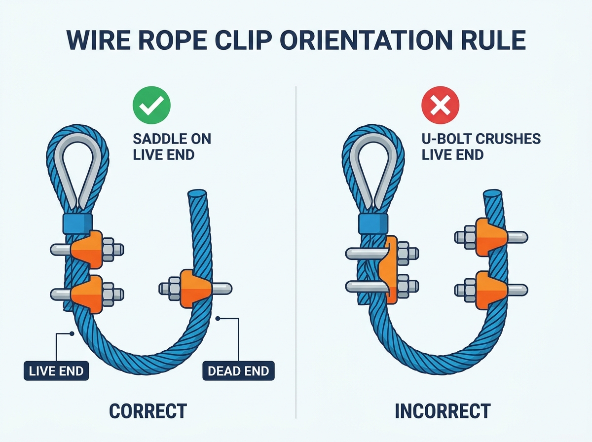
- Orientation is Critical: The "U" section must always contact the dead end of the rope, while the saddle must rest on the live end ("Never saddle a dead horse").
- Torque is Mandatory: Installations require specific torque values and mandatory retightening after the system's initial loading.
The Engineering Baseline: Compliance and Wire Rope Termination
Improper termination remains a leading cause of rigging failure across global job sites. You must understand the business case for precision. Every secure wire rope termination demands strict compliance. ASME B30.26 and OSHA 1926.251 form the ultimate baseline for safety. Following these codes ensures your hardware achieves optimal efficiency. A compliant assembly typically reaches 80% of the nominal breaking strength. The remaining 20% accounts for the termination loss. You cannot recover this lost strength.
Wire rope clips rely entirely on friction to hold a load. This friction mechanism distributes the load across multiple grip points. Insufficient clips inevitably result in dangerous rope slippage. A slipping load threatens lives and destroys expensive equipment. Conversely, applying too many clips introduces different risks. Over-torqued clips crush the steel wires. This damage destroys the inner core and reduces total load capacity. You must strike the perfect mechanical balance.
Every wire rope fitting represents a potential weak point in the system. Site managers often face unexpected equipment stresses. Heavy winds and dynamic loads test these weak points daily. Using standardized baseline metrics removes dangerous guesswork from field operations. Strict compliance ultimately limits enterprise liability. Operators must inspect these vulnerabilities before every major lift. You protect your team when you prioritize proper engineering baselines.
Standard Clip Quantity Requirements by Rope Diameter
Clip quantity cannot be eyeballed under any circumstances. Procurement teams and site safety managers must follow strict frameworks. You must align your hardware inventory using verified sizing charts. Standard operating procedures depend on these exact numbers.
We rely on general sizing baselines for forged hardware. Different diameters demand specific clip counts. Review the essential requirements below:
- 1/8" to 5/16" Diameter: Minimum 2 clips.
- 3/8" to 9/16" Diameter: Minimum 3 clips.
- 5/8" to 3/4" Diameter: Minimum 4 clips.
- 7/8" to 1" Diameter: Minimum 5 clips.
- 1-1/8" to 1-1/4" Diameter: Minimum 6 clips.
Always consult the specific manufacturer’s lookup table. Strand construction can alter these fundamental requirements. Fiber core ropes behave differently under clamping pressure. They compress more than solid steel cores.
You must also adjust formulas when using malleable clips. Malleable hardware serves non-overhead, light-duty commercial fencing or guardrails. Standard practice often requires adding at least one additional clip. This addition compensates for the lower material strength of cast iron.
Standard Clip Quantity Guidelines
| Rope Diameter | Forged Clip Minimum | Malleable Clip Minimum (Non-Overhead) |
| 1/8" to 5/16" | 2 | 3 |
| 3/8" to 9/16" | 3 | 4 |
| 5/8" to 3/4" | 4 | 5 |
| 7/8" to 1" | 5 | 6 |
Calculating Wire Rope Clamp Spacing and Turnback
Accurate wire rope clamp spacing guarantees the assembly holds tension securely. Engineers universally calculate this distance as six times the rope diameter. We write this standard formula as 6 x D. You must measure this distance precisely. Spacing them closer severely compromises holding power. The friction cannot distribute evenly across the strands. Spacing them further apart reduces the effectiveness of the termination point. The rope can bow or flex between the clamps.
Turnback length requires precise measurement before installation. Turnback is the amount of dead end rope folded back. This folded section accommodates the necessary clips and spacing. Turnback length must cover the clips plus the empty spacing blocks. Consider a standard 1/2" rope requiring three total clips. The spacing equals three inches between each clip. The turnback must be explicitly measured along the entire length. You must leave enough room at the end. This ensures the last clip avoids sitting on the thimble. It also prevents the clip from slipping off the absolute tip.
Heavy-duty applications require proper thimble integration. A thimble prevents the eye from kinking under heavy load. It stops friction from fraying the inner steel strands. Spacing measurements begin directly at the base of the thimble. You place the first clip near the dead end tip. You then place the second clip right against the thimble. Finally, you space the remaining clips evenly between them. This sequence locks the thimble tightly in place.
Installation Risks and Common Hardware Failures
Riggers must follow the strict orientation rule flawlessly. A standard U bolt clip consists of three main components. It features a U-bolt, a forged saddle, and two locking nuts. The saddle must always sit on the live side. The live side represents the load-bearing segment of the rope. Reversing even one clip drastically reduces termination strength. The U-bolt crushes the live wires and triggers premature failure. Industry veterans call this rule "never saddle a dead horse." You must memorize this phrase.
Torque loss presents a massive danger during the initial load. Wire ropes stretch and reduce in diameter under tension. The steel strands pull tighter together. This physical change causes the assembly to lose initial torque. Clamping pressure drops significantly after the first major lift. All nuts require immediate retorquing to the recommended foot-pounds. This mandatory step prevents catastrophic slippage during subsequent operations. You must schedule this retorquing into your operational timeline.
Mixing hardware types creates unpredictable failure thresholds. You must never mix different brands in a single assembly. Combining galvanized steel and stainless steel causes uneven load distribution. Galvanic corrosion can also occur between mismatched metals. Avoid mixing forged clips and standard cable clamps. Inconsistent hardware styles compromise the structural integrity. Your entire termination becomes a major safety liability. Stick to one manufacturer and one material grade per assembly.
Avoid these three critical installation errors:
- Installing the saddle on the dead end of the rope.
- Failing to use a calibrated torque wrench during installation.
- Skipping the mandatory post-load retightening procedure.
Shortlisting Rigging Hardware for Your Application
Evaluating hardware styles helps you build a safer lifting system. We constantly compare U-Bolt designs against Fist Grip clips. U-Bolt clips remain the absolute industry standard. They are highly accessible and incredibly cost-effective. You can find them at almost any industrial supplier. However, they require strict adherence to the live/dead end orientation rule. Operator error remains a significant risk during fast-paced installations. You must train your crew thoroughly.
Fist Grip clips feature forged saddles on both halves. Installers cannot put them on backward accidentally. This design completely eliminates the notorious "dead horse" orientation risk. Fist Grips often require fewer clips per termination point. This advantage saves valuable installation time on large projects. They do carry a higher upfront procurement cost. Many safety managers prefer them despite the price tag. The reduced risk of human error justifies the investment.
Material selection dictates the lifespan of your rigging hardware. Consider your operating environment carefully. Drop-forged galvanized steel handles heavy-duty lifting flawlessly. It performs exceptionally well in standard outdoor construction environments. The zinc coating provides adequate rust protection. Type 316 stainless steel handles extreme corrosive exposure. Marine environments, wastewater plants, and chemical facilities demand stainless steel. Corrosion resistance outweighs raw tensile capacity in these harsh conditions.
Maintain strict sourcing criteria for all critical hardware. Only purchase components from reputable industrial suppliers. Your supplier must provide fully traceable mill certificates. They must also deliver explicit ASME and OSHA compliance documentation. Never trust unverified hardware for overhead lifting applications. Counterfeit rigging hardware floods the global market. You must verify the origin of every single clip.
Hardware Type Comparison Chart
| Clip Type | Orientation Risk | Cost Profile | Installation Speed |
| Forged U-Bolt | High (Requires strict live/dead alignment) | Highly cost-effective | Standard |
| Fist Grip (Double Saddle) | Zero (Cannot be installed backward) | Higher upfront cost | Faster |
Conclusion
Building a secure rigging assembly demands absolute mathematical precision. Verify your rope diameter against established engineering tables before buying hardware. Calculate the exact turnback length to ensure optimal clamp spacing. Always keep a calibrated torque wrench on the job site. Select the right class of hardware for your specific environment. Commit to a strict post-load retightening protocol for every assembly. Prioritize safety and compliance to achieve zero-fail lifting operations.
FAQ
Q: Can I use cable clamps instead of wire rope clips?
A: The terms are often used interchangeably, but "cable clamps" generally refers to lighter-duty hardware. This includes stamped electrical cable clips or malleable hardware. These are not rated for heavy loads. Always specify "forged wire rope clips" for load-bearing rigging to ensure maximum safety and compliance.
Q: What happens if I install a U bolt clip backward?
A: Installing the U-bolt over the live end crushes the load-bearing wires. This mistake reduces the overall breaking strength of the wire rope assembly by up to 40%. It violates strict safety regulations and drastically increases the risk of a catastrophic load drop.
Q: Do I need a torque wrench to install wire rope clips?
A: Yes. Under-tightening leads to dangerous rope slippage. Over-tightening crushes the inner core of the wire rope. Manufacturer-specified torque values must be strictly followed. A calibrated torque wrench guarantees you achieve the exact required clamping force for safe operations.
Q: How often should wire rope fittings be inspected?
A: Hardware should be visually inspected prior to every single shift. A documented, comprehensive inspection measuring torque, corrosion, and wire integrity must occur at regular intervals. Base this schedule on usage frequency and environmental conditions to maintain safety standards.
Q: Does the type of wire rope core affect the number of clips needed?
A: Yes. Standard tables usually apply to Independent Wire Rope Core (IWRC) or wire strand core. Fiber core ropes compress differently under pressure. They often require special considerations or additional clips. Always verify exact requirements with the clip manufacturer before installation.

 English
 العربية
 Français
 Русский
 Español
 Português
 Deutsch
 italiano
 日本語
 한국어
 Nederlands
 Tiếng Việt
 ไทย
 Polski
 Türkçe
 አማርኛ
 ພາສາລາວ
 ភាសាខ្មែរ
 Bahasa Melayu
 ဗမာစာ
 தமிழ்
 Filipino
 Bahasa Indonesia
 magyar
 Română
 Čeština
 Монгол
 қазақ
 Српски
 हिन्दी
 Slovenčina
 Slovenščina
 Norsk
 Svenska
 українська
 Ελληνικά
 Suomi
 Հայերեն
 עברית
 Dansk
 اردو


