Selecting the correct equipment for load-bearing operations involves much more than simply matching a weight limit. You must carefully balance engineering trade-offs between tensile strength, bending flexibility, and harsh environmental resilience. Improper specification creates severe risks for your daily operations. Using the wrong construction can cause premature fatigue failure and accelerate expensive equipment wear. It also risks non-compliance with strict OSHA and ASME safety standards, leading to unacceptable operational downtime.
We designed this guide to help you navigate these complex choices effectively. We provide procurement teams, engineers, and site managers an evidence-based framework. Through this guide, you will learn how to evaluate and select the exact construction necessary for safe, highly efficient heavy lifting operations.
Key Takeaways
- Lifting capacity is governed by the Working Load Limit (WLL) and an application-specific design factor (typically 5:1 for standard lifting, higher for personnel).
- Wire rope selection requires a strict trade-off analysis: highly flexible ropes are more susceptible to abrasion, while abrasion-resistant ropes are more prone to bending fatigue.
- Core type (IWRC vs. FC) directly impacts the rope’s crush resistance and behavior on multi-layer winch drums.
- Accurate measurement of wire rope size and compatibility with existing sheaves and rigging hardware are mandatory for safe implementation.
Evaluating Wire Rope vs. Alternatives for Heavy Lifting
Engineers face a critical business problem when designing a hoisting system. You must decide when to specify a lifting cable over traditional alloy chain slings or synthetic straps. Each material serves a specific purpose, but steel cables offer unique advantages for continuous heavy hoisting.
One major advantage is the predictability of failure. Rigid alloy chains carry extreme loads, but they tend to yield and snap suddenly when overloaded. In contrast, steel wire rope features dozens or hundreds of redundant load-bearing wires. This redundant design allows operators to perform a visual inspection and spot broken outer wires long before a catastrophic failure occurs. You gain a crucial warning window to replace the equipment safely.
Furthermore, steel cables offer a superior weight-to-strength ratio compared to heavy lifting chains. This metric is especially critical for mobile crane applications. Cranes operate under strict gross weight limitations. If your rigging is too heavy, you sacrifice valuable lifting capacity. Cables deliver the necessary strength without adding excessive dead weight to the boom.
However, we must clarify certain limitations and assumptions. Steel cable is not universally superior in every scenario. It remains highly vulnerable to kinking and crushing if spooled incorrectly onto a drum. You will also damage the strands quickly if you use them without appropriate rigging hardware, such as thimbles or proper sheaves. Acknowledging these limitations ensures you deploy the equipment safely.
The Core Evaluation Framework: Strength, Fatigue, and Abrasion
To choose the right equipment, you need a solid evaluation framework. The first step involves understanding the difference between Working Load Limit (WLL) and Minimum Breaking Force (MBF). Manufacturers test their products to find the MBF, which represents the exact point of destructive failure. However, you never lift loads at the MBF. Instead, industry standards like ASME B30.9 dictate a strict safety design factor. For general hoisting, we apply a 5:1 ratio. This means the WLL is exactly 20% of the manufacturer’s breaking strength. For personnel lifting, that safety factor jumps even higher.
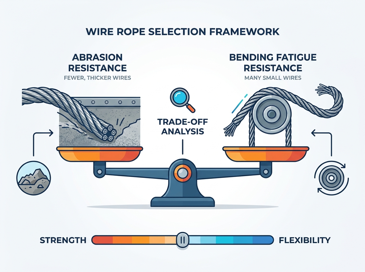
Next, you must navigate the fatigue versus abrasion trade-off. This is where true rigging expertise comes into play. You cannot maximize both metrics simultaneously.
Abrasion Resistance: Ropes designed for harsh, abrasive environments feature fewer, thicker outer wires. These thick wires resist surface wear when dragging across rough terrain or rubbing against structures. However, these thick wires are stiff. They snap easily under repeated bending cycles over small sheaves.
Bending Fatigue Resistance: Conversely, ropes built for constant spooling over sheaves and drums use many small, thin outer wires. They flex easily and endure constant bending. The downside is clear: those thin wires wear down rapidly if dragged across rough surfaces.
We strongly recommend referencing the following trade-off chart during your evaluation process.
Engineering Trade-off: Abrasion vs. Flexibility
| Construction Type | Outer Wire Characteristics | Primary Strength | Primary Weakness | Ideal Application |
| 6x7 Class | Few, very thick wires | Maximum abrasion resistance | Poor bending fatigue life | Static dragging, guylines |
| 6x19 Class | Medium thickness | Balanced durability | Moderate in both extremes | General purpose hoisting |
| 6x36 Class | Many thin wires | Maximum bending flexibility | Highly vulnerable to abrasion | Complex crane routing |
Crush resistance forms the final pillar of this framework. When you wrap a cable tightly around a drum, the underlying layers face immense pressure. A cable lacking proper internal support will flatten. Once it flattens, it loses its structural integrity and becomes dangerous. Multi-layer spooling environments require maximum crush resistance to maintain safe operations.
Decoding Construction Classes and Core Types
Manufacturers use a specific nomenclature to describe their products. You will frequently see numbers like "6x19" or "6x36". The first number represents the total number of strands wrapped around the core. The second number represents the nominal number of individual wires inside each strand. Lay direction also matters. "Regular Lay" means the wires twist in the opposite direction of the strands, providing excellent stability. "Lang Lay" means the wires and strands twist in the same direction, improving fatigue life but making the assembly prone to untwisting if both ends are not secured.
When selecting a crane wire rope, you generally choose between three main categories:
- 6x19 Class: This is the general-purpose industry standard. It offers a reliable, middle-ground balance between fatigue life and abrasion resistance.
- 6x36 Class: This class provides higher flexibility. We recommend it for complex crane systems routing through multiple sheaves.
- Rotation-Resistant Ropes: These feature multiple layers of strands wrapped in opposing directions. They are absolutely necessary for single-part hoisting where the load must not spin in mid-air. However, they demand much stricter handling protocols to prevent internal damage.
Beyond the strands, you must select the appropriate internal core. The core provides the foundation for the outer strands, and your choice dictates the rope's behavior under heavy strain.
- Independent Wire Rope Core (IWRC): This core uses a smaller steel assembly inside the main strands. It provides maximum strength and exceptional crush resistance. IWRC is mandatory for high-heat environments where synthetic materials would melt.
- Fiber Core (FC): This core utilizes sisal or synthetic fibers. It offers superior flexibility and acts as a sponge, retaining internal lubrication much better than steel. However, it compromises overall breaking strength and will collapse easily on multi-layer drums. It is also strictly forbidden in extreme heat applications.
Specifications: Wire Rope Size, Finish, and Environment
Accurate measurement is critical for safety. Determining the exact wire rope size requires measuring the true diameter across the widest part of the strands, not the narrow valleys. Using oversized or undersized equipment introduces immediate operational risks. If a cable is too large for a sheave groove, the groove walls will crush the strands as it passes through. If the cable is too small, it will pinch at the bottom of the groove and wear down rapidly.
Engineers manage these risks using the D/d Ratio. This is the critical ratio of the sheave diameter (D) divided by the rope diameter (d). This mathematical metric dictates the required flexibility of your chosen assembly. A larger sheave creates a gentle bend, reducing stress. A small sheave forces a sharp bend, exponentially increasing the bending stresses. If your equipment dictates a tight D/d ratio, you must select a highly flexible construction class to prevent sudden snapping.
Environmental resilience is equally important when specifying an industrial wire rope. Steel degrades quickly if left unprotected. You must match the finish to your operating environment:
- Bright Wire: This is standard uncoated, lubricated steel. It boasts excellent fatigue properties and serves well for most protected, indoor industrial applications.
- Galvanized: Manufacturers coat these wires in zinc. Galvanization offers moderate corrosion resistance, making it ideal for marine environments or outdoor static applications. However, the zinc coating slightly reduces the overall bending fatigue life compared to bright wire.
- Stainless Steel: This material provides maximum corrosion resistance against harsh chemicals and saltwater. You pay a premium for it, and it generally features a significantly lower nominal strength compared to high-carbon bright steel.
Implementation: Hardware Compatibility and Rigging Safety
Your hoisting system is only as strong as its weakest connection point. Matching the correct hardware to your rigging rope is non-negotiable. Poor terminations will cause the assembly to fail long before it reaches its theoretical working load limit.
Different end treatments yield drastically different efficiency ratings. For instance, factory-installed swaged sockets generally preserve 100% of the cable's breaking strength. In contrast, standard U-bolt clips and clamps usually deliver only an 80% efficiency rating. You must factor this 20% strength reduction into your overall load calculations.
Field installations carry significant rollout risks. We commonly see adoption failures caused by basic errors. Follow these critical implementation steps:
- Never saddle a dead horse: When installing U-bolt clamps, the U-bolt section must sit entirely on the "dead" tail end of the line. The solid forged saddle must press against the "live" tension-bearing side. Installing them backward crushes the live side and drastically weakens the connection.
- Proper initial spooling: You must properly seat the cable on the initial drum wrap under significant tension. A loose first layer guarantees that subsequent wraps will bite down, crush the lower layers, and destroy the assembly.
- Verify drop-forged hardware: Ensure you use drop-forged clips for heavy lifting operations. Malleable iron clips are only suitable for non-critical, light-duty applications.
- Torque verification: Always apply the manufacturer's recommended torque to your clamp nuts. Check them again after the first test lift, as the strands will compress and loosen the initial grip.
Finally, proper deployment of a lifting wire rope requires a strict maintenance baseline. Establish a documented lubrication schedule to prevent internal friction between strands. Implement compliance-based visual inspection intervals to document broken wires, signs of kinking, or visible core protrusion.
Conclusion
Choosing the correct equipment demands a comprehensive decision matrix. Your final selection must successfully balance your specific WLL requirements, the unavoidable fatigue-versus-abrasion trade-off, harsh environmental conditions, and strict hardware compatibility.
We advise procurement teams to avoid the common trap of over-specifying a single metric. Prioritizing massive breaking strength at the complete expense of bending flexibility will result in an assembly that destroys itself on your sheaves. You must balance the physical realities of your hoisting setup.
Take action before your next heavy lift. We highly recommend consulting directly with a certified rigger or structural engineer to finalize your technical specifications. Secure custom-swaged assemblies from reputable manufacturers rather than attempting risky field fabrications for critical loads. Proper planning keeps your operations efficient, compliant, and fundamentally safe.
FAQ
Q: What is the standard safety factor for lifting wire rope?
A: For general lifting and rigging operations, the industry standard design factor is 5:1. This means the Working Load Limit is 20% of the manufacturer's Minimum Breaking Force. If you are lifting personnel, OSHA and ASME regulations dictate a much higher safety factor, typically 10:1.
Q: How do I know when my crane wire rope needs replacement?
A: You must replace it based on objective criteria during visual inspections. Look for a specific number of broken wires within a single lay length (as defined by ASME standards). You must also discard it immediately if you spot visible kinking, bird-caging, severe abrasion, or internal core protrusion.
Q: Can I use any cable clamp for lifting operations?
A: No. You must use heavy-duty, drop-forged clips for overhead lifting. Never use malleable iron clips, which are prone to cracking under dynamic loads. Furthermore, you must install them correctly (never saddle a dead horse) and torque the nuts to the exact manufacturer specifications.
Q: Why is my wire rope crushing on the winch drum?
A: Crushing usually occurs due to two main reasons. First, you may have installed it with insufficient tension, causing upper layers to bite into the loose lower wraps. Second, you might have incorrectly specified a Fiber Core (FC) instead of an Independent Wire Rope Core (IWRC) for multi-layer spooling.

 English
 العربية
 Français
 Русский
 Español
 Português
 Deutsch
 italiano
 日本語
 한국어
 Nederlands
 Tiếng Việt
 ไทย
 Polski
 Türkçe
 አማርኛ
 ພາສາລາວ
 ភាសាខ្មែរ
 Bahasa Melayu
 ဗမာစာ
 தமிழ்
 Filipino
 Bahasa Indonesia
 magyar
 Română
 Čeština
 Монгол
 қазақ
 Српски
 हिन्दी
 Slovenčina
 Slovenščina
 Norsk
 Svenska
 українська
 Ελληνικά
 Suomi
 Հայերեն
 עברית
 Dansk
 اردو


