Incorrect hardware sizing compromises structural integrity. It leads to rigging failures, premature hardware fatigue, or inadequate tensioning capability. You cannot afford to guess when tensioning critical systems. In industrial, marine, or architectural applications, selecting hardware based on assumptions carries significant safety and compliance risks. Every single component in your assembly must pull its own weight reliably. Calculated load and take-up requirements must drive every hardware decision you make. This guide provides a clear, engineering-aligned framework for calculating required dimensions. You will learn how to evaluate capacity accurately. Finally, we will help you confidently choose the right components for your specific assembly. Let us dive into the mechanics of precise measurement. We will explore the technical specifications you need to build secure, long-lasting tension systems.
Key Takeaways
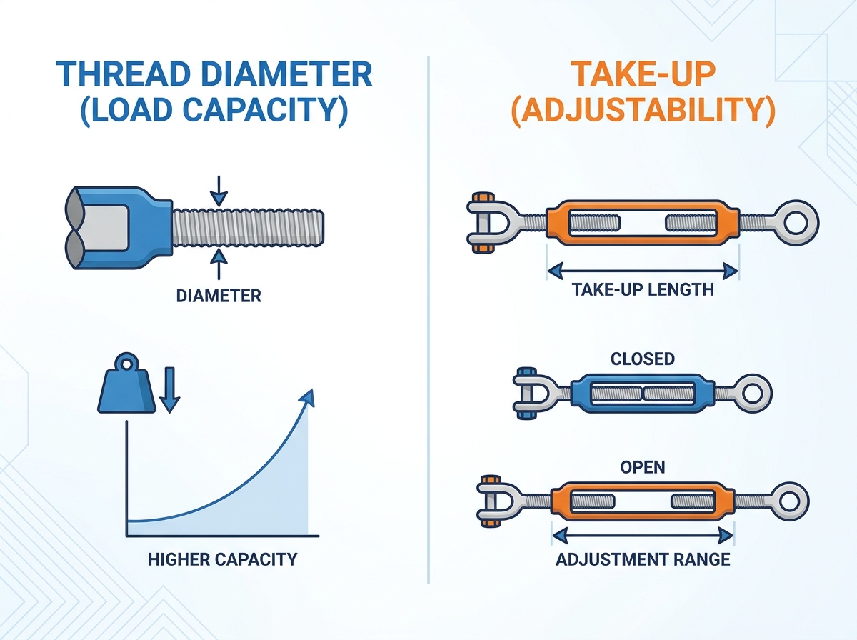
- Size denotes two distinct measurements: Thread diameter (dictating load capacity) and take-up length (dictating tensioning adjustability).
- Working Load Limit (WLL) is non-negotiable: Sizing must be based on the WLL, factoring in the safety ratio for your specific application, never the breaking strength.
- End fittings impact overall capacity: A hook-end turnbuckle fundamentally alters the safe operating load compared to a jaw or eye fitting of the exact same thread size.
- Material dictates longevity: The choice between a galvanized turnbuckle and a stainless steel variant depends heavily on the corrosive realities of the deployment environment.
Defining the Baseline: The Two Core Components of Turnbuckle Size
When you look at a standard specification sheet, you will see two numbers. For example, a common label might read 1/2" x 12". The first number always measures the thread diameter. This dimension dictates the core tensile strength of the device. It tells you exactly how much weight the hardware can safely hold under normal conditions. Engineers rely on thread thickness as the primary indicator of physical endurance. Thicker threads resist stripping and deformation under heavy strain. Unified National Coarse (UNC) threads are typically standard in these heavy-duty applications.
The second number represents the take-up length. Take-up defines the total linear distance the central body can contract or expand. This gives you the functional adjustment window for your assembly. If your system requires frequent tightening, you need a generous take-up length to avoid constant re-rigging.
Understanding the difference between closed length and open length remains equally critical. These dimensions determine your physical installation fit. The closed length represents the absolute minimum distance from end to end when fully tightened. You must ensure this fully closed unit fits into your designated assembly space. Conversely, the open length tells you the maximum reach before tensioning begins. Measuring both extremes prevents frustrating installation delays on the job site. This baseline knowledge helps you determine the perfect turnbuckle size for your specific rigging requirements.
Evaluating Turnbuckle Load: Working Load Limit (WLL) vs. Breaking Strength
You must calculate static and dynamic forces before selecting any hardware. Static forces refer to the consistent dead weight of the suspended load. Dynamic forces introduce variables like high winds, impact shocks, or mechanical vibration. You must calculate both metrics to determine the true tension required for the wire rope tensioner in your specific project. A bridge cable experiences drastically different stressors than a static warehouse beam.
Next, strictly evaluate the manufacturer-rated WLL. Base your allowable turnbuckle load capacity entirely on this verified number. Rigging standards, such as ASME B30.26, typically mandate a 5:1 design factor for a general rigging turnbuckle. This ratio means the theoretical breaking point is five times higher than the permitted working limit. This built-in safety margin accounts for sudden environmental shocks or minor material fatigue over time. You should never treat the WLL as a suggestion. It serves as a strict operational boundary enforced by safety regulators worldwide.
Finally, avoid the breaking strength fallacy at all costs. Some buyers mistakenly size their hardware based on ultimate breaking strength. This practice creates dangerous, hidden under-sizing within the system. The metal body will warp, elongate, or permanently deform under normal operational stress long before it actually snaps. Relying on breaking strength eliminates your safety margin entirely. It puts human lives, expensive machinery, and critical infrastructure at immense risk of sudden catastrophic failure.
Calculating Take-Up: Securing Adequate Adjustment Distance
Cable stretch happens in two distinct phases during deployment. Constructional stretch occurs immediately as the individual wire strands compress under the initial applied load. Elastic stretch happens gradually over time as temperature changes and continuous strain affect the metal. A reliable cable tensioner needs enough take-up to compensate for future slack. If you calculate this incorrectly, you face complete system re-rigging. A simple engineering rule of thumb suggests leaving at least half of your take-up window available for future adjustments.
Installation clearance also dictates your sizing choices heavily. You must evaluate the physical space available in the surrounding assembly. Will the central body fit when fully extended? Measure the clear gap between your rigid anchor points carefully. Obstructions like concrete walls or intersecting steel beams often restrict how much physical space you actually have to rotate the device.
Always avoid the dangerous bottom-out risk during initial setup. A severe implementation warning exists here for all field technicians. If you install a tensioning device fully closed, you leave zero room for future tightening. When the wire rope inevitably stretches, you cannot take up the resulting slack. The system becomes completely useless. Ensure you leave adequate thread exposed during initial installation to guarantee long-term adjustability.
End Fitting Selection: How Configurations Alter Sizing Parameters
Your choice of end attachments heavily influences the overall capacity of the assembly. Jaw and eye fittings offer exceptional high-capacity performance. They work best for secure, closed-loop connections where structural integrity remains paramount. A Jaw/Eye or Jaw/Jaw configuration typically maintains the maximum Working Load Limit for any given thread diameter. The closed loop design prevents the connection point from slipping off under extreme vibration or sudden slack. Engineers strongly prefer these enclosed designs for overhead lifting and permanent structural suspensions.
Hook fittings prioritize speed and convenience over sheer holding capacity. They suit temporary connections or assemblies requiring frequent disassembly and adjustment. However, hooks carry a major implementation risk in the field. They inherently reduce the WLL of the entire unit. Often, choosing a hook drops the safe rating by up to 33% compared to enclosed eyes or jaws. The open mouth of the hook can physically spread outward under heavy continuous load. You must proactively adjust your sizing parameters upward to compensate for this inherent structural vulnerability.
End Fitting Capacity Comparison
| Fitting Type | Primary Application | WLL Retention | Implementation Risk Factor |
| Jaw / Jaw | Permanent structural rigging | 100% (Maximum capacity) | Low (Closed loop prevents slipping) |
| Eye / Eye | Guided wire tensioning | 100% (Maximum capacity) | Low (Requires shackle for attachment) |
| Hook / Hook | Temporary quick-release loads | Reduced by ~33% | High (Prone to spreading under stress) |
Material Evaluation: Matching Hardware to Environmental Realities
Your deployment environment directly dictates hardware lifespan and reliability. A galvanized turnbuckle features robust drop-forged carbon steel construction. This manufacturing process makes it ideal for heavy-duty, industrial, or static outdoor applications. Forging aligns the metal grain structure, adding immense strength. The hot-dipped zinc coating provides excellent defense against standard weather patterns and occasional moisture. It remains highly cost-effective, extremely durable, and handles high working loads efficiently. Many construction sites rely exclusively on galvanized variants for these exact reasons.
Stainless steel (Type 316) serves a completely different, highly specialized purpose. You absolutely need it for marine environments, architectural cable railing, or highly corrosive chemical exposure. The presence of molybdenum in Type 316 alloy actively resists saltwater pitting and aggressive industrial chemicals. Consider the upfront cost versus long-term performance trade-off carefully. Stainless steel generally carries a higher initial purchase price. It also possesses a slightly lower WLL than a similarly sized carbon steel unit. However, it completely prevents rust-induced structural failure over a long-term deployment. Choosing the wrong material guarantees premature replacement and unexpected safety hazards.
Turnbuckle Selection Framework & Implementation Risks
Follow this shortlisting logic to finalize your turnbuckle selection accurately. Methodical evaluation prevents costly purchasing mistakes in the field.
- Define the maximum expected static and dynamic load, then add the required safety factor.
- Select the minimum thread diameter needed to meet or exceed that calculated WLL.
- Determine the necessary take-up length required for proper initial and long-term tensioning.
- Choose end fittings based strictly on your specific connection points and required security.
- Specify the manufacturing material based on environmental exposure and corrosion threats.
Common rollout risks will quickly ruin a well-calculated plan. You must train your field teams to recognize and avoid these specific hazards during installation.
- Angular Loading: Tensioning devices only handle strictly straight-line pulls. Side-loading drastically reduces the safe capacity. It actively bends the threaded rod and instantly compromises the entire assembly. Always ensure the force applies directly along the central axis.
- Thread Galling: Adjusting stainless steel units under intense continuous load creates immense friction. Without proper anti-seize lubrication, the threads will physically fuse together through cold welding. This irreversible damage renders the hardware completely useless.
- Mismatched Hardware: Your various connection components must integrate smoothly. Ensure the chosen eye diameter perfectly aligns with the shackle pin or wire rope thimble it attaches to. A sloppy fit causes uneven wear and dangerous point-loading on the metal.
Conclusion
Correct hardware sizing remains an exact, unforgiving science. You must perfectly balance the safe working limit, the take-up adjustment length, and the specific fitting geometry. Guesswork has no place in structural engineering.
Base your final purchasing decision strictly on verified manufacturer load ratings. Do not rely on aesthetic preferences, generalized charts, or estimated breaking strengths. Your equipment must perform flawlessly under the worst possible conditions to protect lives and property.
Consult a rigging hardware specialist or review formal engineering documentation immediately. Take this critical action step especially if your project involves overhead lifting, human suspension, or heavy critical structural loads. Expert validation provides peace of mind and ensures total regulatory compliance.
FAQ
Q: How is a turnbuckle measured?
A: Measured by thread diameter and the length of the take-up window (e.g., 5/8" x 9"). The thread determines the capacity, while the take-up denotes the adjustment length.
Q: Can I use any turnbuckle for overhead lifting?
A: No. Only specifically rated drop-forged turnbuckles (usually galvanized steel) with secure fittings (jaw/eye) should be considered, and only if explicitly approved by the manufacturer for lifting. Hook ends should never be used for lifting.
Q: What happens if my turnbuckle is too small for the load?
A: The threads may strip, the body may deform, or the end fittings (especially hooks) may bend and release the load, causing catastrophic failure.
Q: How much take-up do I need for a 50-foot cable run?
A: This depends on the cable type (e.g., 1x19 vs. 7x19) and expected temperature fluctuations. A standard engineering recommendation is to allow at least 1-2% of the total cable length in take-up capacity.
Q: Why is the WLL lower on a hook-to-hook turnbuckle?
A: Because the open design of a hook makes it the weakest point. Under extreme tension, a hook will bend outward and release the connection long before the threaded rod breaks.

 English
 العربية
 Français
 Русский
 Español
 Português
 Deutsch
 italiano
 日本語
 한국어
 Nederlands
 Tiếng Việt
 ไทย
 Polski
 Türkçe
 አማርኛ
 ພາສາລາວ
 ភាសាខ្មែរ
 Bahasa Melayu
 ဗမာစာ
 தமிழ்
 Filipino
 Bahasa Indonesia
 magyar
 Română
 Čeština
 Монгол
 қазақ
 Српски
 हिन्दी
 Slovenčina
 Slovenščina
 Norsk
 Svenska
 українська
 Ελληνικά
 Suomi
 Հայերեն
 עברית
 Dansk
 اردو


