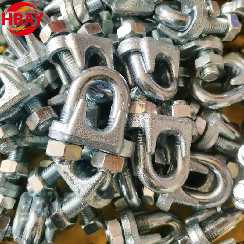
A wire rope termination can look secure with two clips, but appearance alone does not establish whether the connection has been assembled correctly. A change in rope diameter, clip construction, or application can change the required number of clips.
For example, a 1/2-inch steel wire rope may require three drop-forged U-bolt clips under a specified OSHA construction-industry table, while larger diameters require different quantities and spacing. Those figures cannot be applied indiscriminately to every clip design or rope construction.
Before selecting wire rope clips, buyers and installers need to identify the rope, termination type, applicable standard, and manufacturer's installation requirements. The clip count is only one part of a reliable connection.
How Many Wire Rope Clips Do You Need?
The required number of wire rope clips depends on the rope diameter, clip design, rope construction, and intended application. The manufacturer's instructions and applicable regulations should determine the final quantity.
Factors Influencing the Number of Clips Needed
Rope diameter is the starting point, but it is not the only consideration.
The following factors influence clip selection and installation:
Wire rope diameter: Larger ropes generally require different clip quantities, sizes, and spacing.
Clip construction: Drop-forged U-bolt clips, malleable clips, and double-saddle designs may have different installation requirements.
Rope construction: Strand arrangement, core type, and rope grade can affect the applicability of a manufacturer's instructions.
Termination configuration: A thimble-eye termination is not necessarily installed in the same way as a specialized rope connection.
Turnback length: Sufficient rope must be available to form the termination and position the clips correctly.
Operating conditions: Loading, vibration, corrosion, and other environmental factors affect the suitability of the complete assembly.
Adding clips without following a tested installation procedure does not automatically increase the termination's allowable capacity.
Recommended Number of Wire Rope Clips by Diameter
For certain U-bolt wire rope clip applications, OSHA provides minimum clip quantities and spacing in 29 CFR 1926.251, Table H-2.
The following figures apply to the table's specified improved plow steel wire rope and drop-forged clip category.
Wire Rope Diameter
Minimum Drop-Forged Clips
Minimum Clip Spacing
1/2 in.
3
3 in.
5/8 in.
3
3-3/4 in.
3/4 in.
4
4-1/2 in.
7/8 in.
4
5-1/4 in.
1 in.
5
6 in.
1-1/8 in.
6
6-3/4 in.
1-1/4 in.
6
7-1/2 in.
1-3/8 in.
7
8-1/4 in.
1-1/2 in.
7
9 in.
These values are not a universal installation chart for all wire rope clips.
For example, the table specifies three drop-forged clips for a 1/2-inch rope and five for a 1-inch rope under the stated conditions.
Other rope constructions, clip materials, or specialized applications may require different arrangements.
Before installation, confirm that the selected clip manufacturer's specifications cover the actual rope and intended use.
Manufacturer Instructions vs. OSHA Requirements
Manufacturer instructions and OSHA regulations serve related but different purposes.
Manufacturer installation instructions describe the tested requirements for a particular product. They may specify clip quantity, spacing, turnback length, tightening torque, and additional installation conditions.
OSHA regulations establish requirements for activities within their scope. Where a relevant regulation applies, the installation must satisfy those requirements.
The correct approach is to identify all applicable requirements and verify that the selected product can meet them.
If the manufacturer's instructions and regulatory requirements appear inconsistent, the installer should seek clarification rather than independently changing the clip count or torque.
Special Rope Constructions and Operating Conditions
Standard installation tables may not cover every wire rope.
Some manufacturer instructions also specify additional clips when a pulley or sheave is used in a particular turnback arrangement.
Such adjustments are product-specific and should not be applied automatically to other clip designs.
For unusual rope constructions or operating conditions, obtain written installation guidance from the manufacturer or a qualified rigging professional.
Correct Installation of Wire Rope Clips
Even the correct number of clips cannot compensate for incorrect orientation, spacing, or tightening.
The following principles apply to conventional U-bolt clip installations where their use is permitted.
The "Never Saddle a Dead Horse" Rule
A conventional U-bolt wire rope clip has two main clamping components: a U-bolt and a saddle.
The live end of the rope is the portion that carries the working load. The dead end is the returned tail.
For a standard U-bolt clip arrangement:
Saddle: Positioned against the live, load-bearing rope.
U-bolt: Positioned over the dead end.
This arrangement is commonly remembered through the phrase Never saddle a dead horse.
Reversing the clip can create excessive compression on the load-bearing portion of the rope and compromise the termination.
The rule applies to this U-bolt configuration. Other clip designs may have different installation instructions.
Proper Spacing Between Clips
Spacing affects how the clips grip the rope along the termination.
For the applications covered by OSHA Table H-2, the specified minimum spacing is six times the rope diameter.
As an example, a 1/2-inch rope has a minimum spacing of 3 inches under that table.
However, spacing must also agree with the selected manufacturer's installation procedure.
Clips should be positioned according to the specified sequence, with the required turnback length available for the complete assembly.
An installer should not estimate spacing by eye or assume that the same arrangement applies to every clip model.
Torque Specifications and Tightening Procedures
Correct tightening is essential because the nuts establish the clamping force between the clip and the rope.
Torque requirements vary according to clip size, design, and manufacturer.
A practical installation procedure includes:
Confirm that the clip and rope sizes match.
Position the clips according to the approved installation arrangement.
Tighten the nuts evenly using the specified sequence.
Use a calibrated torque wrench to reach the manufacturer's required torque.
Verify the completed assembly before placing it into service.
Overtightening can damage components, while insufficient tightening can allow movement or slippage.
Do not transfer a torque value from another manufacturer's chart unless its applicability has been established.
Rechecking Torque After Initial Loading
Wire rope and clip components may settle when the assembly is initially loaded.
For products whose instructions require it, the termination must be subjected to the specified initial loading procedure and the nuts retightened to the required torque.
This step helps restore the intended clamping force after the components have seated.
Subsequent inspection and torque checks should follow the manufacturer's maintenance requirements and the conditions of service.
Common Mistakes When Using Wire Rope Clips
Installation problems often arise from treating wire rope clips as interchangeable hardware rather than components of an engineered termination.
Using Too Few Clips
A termination assembled with fewer clips than required may not achieve its intended holding performance.
For example, using two clips where the applicable installation specification requires three is not an acceptable substitution.
The solution is to verify the clip quantity before cutting the rope or preparing the turnback.
If an assembly has already been installed incorrectly, it should not be used until it has been evaluated and corrected according to the applicable procedure.
Incorrect Saddle and U-Bolt Placement
Reversed U-bolt clips are a recognizable installation error.
Because the two sides of the clip can appear similar, installers may position the saddle against the dead end instead of the live end.
The orientation should be checked during installation and final inspection.
For a conventional U-bolt clip, the saddle belongs on the live rope, and the U-bolt belongs on the dead end.
Skipping Torque Checks
A connection can appear tight without meeting the specified torque.
Common problems include uneven nut tightening, unsuitable tools, and failure to perform the required post-loading checks.
A torque wrench should be used where specified, and the procedure should be documented when the application requires traceability.
The assembly should also be inspected for movement, deformation, or other signs of deterioration during service.
Using the Wrong Clip for the Application
A clip that fits around the rope is not necessarily suitable for the intended load.
Examples of unsuitable selection include:
Choosing a malleable clip for an application requiring an approved forged component
Using a clip without applicable installation documentation
Selecting a clip intended for a different rope diameter
Installing clips over plastic-coated rope without a specifically approved procedure
Using clip terminations in an application where they are prohibited
Correct selection requires confirmation of both the hardware and the application.
Choosing the Right Wire Rope Clip Quality
Wire rope clips differ in material, manufacturing method, geometry, and intended use. These differences affect how the product should be selected.
Forged vs. Malleable Wire Rope Clips
Forged and malleable clips should not be treated as equivalent simply because they have similar external shapes.
Forged wire rope clips are manufactured using a forging process. Certain forged designs are intended for specified load-bearing applications when installed according to their instructions.
Malleable iron clips are manufactured using a casting process and are commonly associated with applications that do not require the same critical load-bearing performance.
The suitability of either type depends on its documented specifications.
For safety-critical applications, buyers should verify that the selected clip construction is expressly approved for the intended use.
Identifying Suitable Load-Bearing Clips
Product selection should begin with the manufacturer's documentation.
Important information includes:
Product model and nominal rope size
Material and manufacturing method
Applicable product standards
Permitted applications and restrictions
Installation instructions and torque requirements
Inspection and replacement criteria
Relevant testing or certification documents, where required
A galvanized or stainless steel finish indicates a material or surface treatment characteristic, not proof of suitability for lifting.
Likewise, the presence of a manufacturer mark does not replace verification of the product's intended use.
Benefits of Heavy-Duty Wire Rope Clips
Properly specified heavy-duty clips may provide a suitable solution for demanding rope termination requirements.
Their advantages depend on the actual design and documented performance rather than the description heavy-duty alone.
Buyers should evaluate material strength, manufacturing consistency, corrosion protection, dimensional compatibility, and the availability of technical instructions.
A higher purchase price or heavier appearance does not automatically indicate a higher permissible load.
When Wire Rope Clips Should Not Be Used
Certain applications require specialized termination methods or prohibit particular clip arrangements.
These include some lifting sling eyes, personnel-support systems, scaffold suspension arrangements, and other regulated installations.
Plastic-coated rope may also be unsuitable for conventional clip installation unless an approved procedure specifically addresses the coating.
Where clip use is restricted, an engineered alternative such as a suitable swaged, socketed, or other approved termination may be required.
The correct alternative depends on the equipment, governing standard, and application.
Types of Wire Rope Clips and Their Uses
Several wire rope clip designs are available, but their names alone do not establish their allowable applications.
DIN 741 Wire Rope Clips
DIN 741-style wire rope clips are commonly encountered in general wire rope hardware applications.
Their construction and dimensions differ from certain heavy-duty forged clip designs.
These clips may be offered with galvanized or stainless steel finishes, depending on the product.
Buyers should not assume that a DIN 741-style clip is approved for overhead lifting or critical load-bearing terminations.
Its intended use, material, and installation requirements must be confirmed from the actual product documentation.
U.S.-Type Wire Rope Clips
U.S.-type clips are available in different constructions, including forged and malleable versions.
The term describes a general product style rather than a universal load rating.
For applications requiring a forged clip, buyers must confirm the actual material and manufacturing process.
A U.S.-type appearance alone is insufficient evidence of compliance with a particular lifting requirement.
Single and Double Flat Cable Clips
Some wire rope fastening products use compact flat or double-bolt arrangements.
These designs may be selected for particular cable layouts, architectural fittings, or other specialized connections.
However, their installation requirements and permitted loads can differ substantially from conventional U-bolt clips.
They should not be substituted into a wire rope termination solely because their dimensions appear compatible.
Oval Wire Rope Clips
Oval and compact clip designs may be used where space or external appearance influences the hardware arrangement.
Their suitability depends on the exact construction and manufacturer's specifications.
For decorative or architectural cable applications, corrosion resistance and appearance may be important.
For load-bearing applications, verified mechanical performance and approved installation procedures take priority.
Fist Grip vs. U-Bolt Clips
The difference between these designs lies mainly in their clamping arrangement.
U-bolt clips use a U-shaped bolt and saddle. Correct orientation is important because the saddle must be positioned on the live rope.
Double-saddle or Fist Grip-style clips use a different clamping configuration, which can reduce certain orientation-related installation errors.
However, neither design should be selected based on appearance alone.
The applicable product instructions must establish the required quantity, spacing, torque, and permitted use.
Maintenance and Inspection of Wire Rope Clips
A correctly installed termination still requires inspection throughout its service life.
Routine Visual Inspections
Inspection should cover the clips, nuts, bolts, and the surrounding rope.
Look for corrosion, cracks, deformation, damaged threads, and visible movement at the termination.
The rope should also be examined for broken wires, crushing, abrasion, or other deterioration near the clamping points.
A termination showing signs of slippage or component damage should be removed from service pending appropriate evaluation.
Checking and Maintaining Proper Torque
Torque checks should follow the manufacturer's instructions and the operating conditions.
Vibration, repeated loading, and environmental exposure may increase the need for inspection.
When checking torque, use the specified equipment and procedure. Do not tighten components indiscriminately in an attempt to compensate for damaged hardware or rope.
If the required torque cannot be maintained, the cause must be investigated before the termination is returned to service.
Signs That Indicate Replacement Is Necessary
Certain conditions require immediate attention.
Inspection Finding
Required Response
Cracked or deformed clip components
Remove the affected assembly from service
Damaged nuts or threads
Do not continue using the defective hardware
Visible rope slippage
Stop use and evaluate the complete termination
Severe corrosion or material loss
Assess against applicable rejection criteria
Crushed or broken rope wires
Inspect the rope and termination under the governing criteria
Missing identification or installation documentation
Verify suitability before further use
Replacement decisions should follow the applicable manufacturer's instructions and safety requirements.
Practices That Help Maintain Service Life
Correct installation is the first step toward reliable long-term performance.
Clips should be selected for the rope diameter and application, installed using the approved procedure, and inspected at intervals appropriate to the service conditions.
Spare components should be stored in clean, dry conditions where practical.
Reusing previously loaded clips should not be assumed acceptable. Some manufacturers discourage reuse or require qualified inspection before further use.
Safety Considerations and Regulations
Wire rope clips are subject to different requirements depending on whether they are used for general rope termination, construction rigging, lifting slings, or other regulated equipment.
OSHA Rules on Wire Rope Clip Usage
OSHA's construction standard, 29 CFR 1926.251, includes provisions for wire rope and U-bolt clip terminations.
Section 1926.251(c)(5) refers to Table H-2 for the number and spacing of U-bolt clips when used to form eyes within the provision's scope.
The regulation also specifies that the U-bolt must contact the dead end of the rope.
However, the same standard restricts forming eyes in wire rope bridles, slings, and bull wires using clips or knots.
These requirements must be read together rather than applying the clip-count table to every lifting assembly.
Applications Requiring Special Restrictions
Wire rope clip terminations are not universally permitted in every lifting or personnel-support application.
Special requirements may apply to:
Wire rope lifting slings and bridles
Suspension scaffold systems
Personnel lifting equipment
Elevator and hoist systems
Specialized crane and industrial installations
The exact restrictions depend on the equipment and governing regulations.
Some applications permit particular engineered terminations under defined conditions, while others prohibit certain clip types or arrangements.
The installer must verify the applicable requirements before selecting a termination method.
Understanding Termination Efficiency
A wire rope termination may have a lower breaking strength than the unmodified rope.
Termination efficiency describes the relationship between the strength of a properly assembled termination and the specified minimum breaking force of the rope.
Some forged clip systems publish efficiency ratings for particular rope sizes and constructions.
These values are product-specific and assume installation according to the relevant instructions.
They should not be applied to all wire rope clips or used as substitutes for a proper working load calculation.
When to Use Fabricated Sling Eyes Instead
Where an application requires a manufactured wire rope sling, a suitable fabricated eye or another approved termination may be necessary.
Possible methods include mechanical splicing, swaged fittings, or socketed terminations, depending on the application.
These alternatives also have their own efficiency ratings, manufacturing requirements, and inspection criteria.
A fabricated termination should not be assumed to retain 100% of the rope's breaking strength without supporting technical data.
The appropriate method should be selected through the applicable standard and a qualified assessment of the lifting requirements.
Conclusion
For a 1/2-inch rope, three clips may be the correct answer under a particular specification. Change the clip construction, rope type, or application, and that answer may no longer apply.
A dependable termination starts with identifying the exact rope and fastening system. Clip quantity, spacing, turnback length, and torque must then come from the relevant installation instructions and safety requirements.
Buyers comparing clip styles or preparing a procurement specification can review the wire rope clip range from ANYUE Rigging Hardware and confirm the required dimensions, material, and documentation before ordering.
FAQ
How Many Wire Rope Clips Do I Need for a 1/2-Inch Rope?
OSHA Table H-2 specifies three drop-forged U-bolt clips for a 1/2-inch improved plow steel wire rope under the table's applicable conditions. Other products or applications may require different specifications.
How Many Wire Rope Clips Are Needed for a 3/4-Inch Rope?
OSHA Table H-2 specifies four drop-forged clips for a 3/4-inch rope within its stated scope. Confirm the selected manufacturer's installation requirements before use.
How Many Wire Rope Clips Do I Need for a 1-Inch Rope?
The OSHA table specifies five drop-forged clips for a 1-inch rope under its applicable conditions, with a minimum spacing of six inches.
Can I Use Two Wire Rope Clips Instead of Three?
Only when the applicable product instructions and governing requirements permit that arrangement. Do not reduce the specified clip quantity.
What Is the Correct Spacing Between Wire Rope Clips?
Spacing depends on the applicable specification. OSHA Table H-2 uses six times the rope diameter for its listed applications, but manufacturer-specific instructions must also be followed.
Which Side of a Wire Rope Clip Goes on the Live End?
For a conventional U-bolt clip, the saddle is placed on the live end, while the U-bolt contacts the dead end.
Do Wire Rope Clips Need to Be Retightened?
Many clip manufacturers require retightening after the initial loading procedure. Follow the specific product instructions and applicable inspection requirements.
Are Malleable Wire Rope Clips Suitable for Lifting?
Malleable clips should not be assumed suitable for critical lifting applications. Use only hardware specifically approved for the intended application and required standard.
Can Wire Rope Clips Be Used to Make Lifting Sling Eyes?
Clip-formed sling eyes are restricted under applicable safety requirements. OSHA construction regulations prohibit certain clip-formed sling eyes, and any exceptions or alternative arrangements must be evaluated under the relevant rules.
How Do I Choose the Correct Wire Rope Clip?
Confirm the rope diameter, rope construction, clip design, intended application, applicable standard, and manufacturer's installation specifications before purchasing or installing the clips.

 English
 العربية
 Français
 Русский
 Español
 Português
 Deutsch
 italiano
 日本語
 한국어
 Nederlands
 Tiếng Việt
 ไทย
 Polski
 Türkçe
 አማርኛ
 ພາສາລາວ
 ភាសាខ្មែរ
 Bahasa Melayu
 ဗမာစာ
 தமிழ்
 Filipino
 Bahasa Indonesia
 magyar
 Română
 Čeština
 Монгол
 қазақ
 Српски
 हिन्दी
 Slovenčina
 Slovenščina
 Norsk
 Svenska
 українська
 Ελληνικά
 Suomi
 Հայերեն
 עברית
 Dansk
 اردو